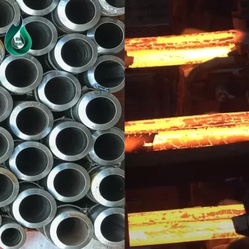
Hydraulic system
The hydraulic system is widely used in various types of machinery and industries. It is an essential part of hydraulics, and hydraulic systems are mainly related to the laws of hydraulic static and dynamic transmission.
In this article, we will explore hydraulic systems together.
What is a hydraulic system?
A hydraulic system is a system that utilizes fluid (usually hydraulic oil) to perform power transmission and control mechanical components and certain types of mechanical equipment.
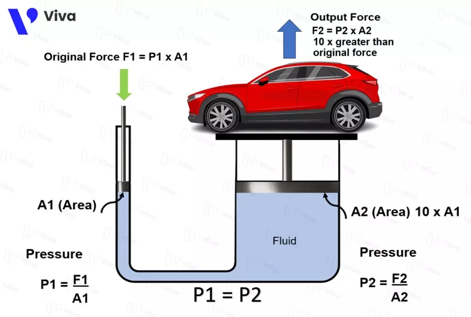
The system operates based on Pascal’s principle, which states that the pressure applied to an incompressible fluid in one area will be transmitted to all other areas without any change in magnitude.

Basic components of a hydraulic system
A hydraulic system includes the following basic components:
- Hydraulic pump: Used to generate pressure for the hydraulic fluid by pumping it into the system. Hydraulic pumps are typically driven by electric motors.
- Hydraulic fluid: This incompressible fluid, often hydraulic oil, has the ability to efficiently transmit pressure.
- Hydraulic cylinder: It is a key component of the hydraulic system and is used to directly drive mechanisms or perform lifting and lowering functions.
- Control valve: Used to control the flow of hydraulic fluid within the system.

Pascal’s Law
Pascal’s Law, also known as Pascal’s principle, is a physical law related to the field of fluid mechanics. It is named after the French physicist Blaise Pascal.
Pascal’s principle states that “Pressure applied to an incompressible fluid in a confined space is transmitted uniformly and without any change in all directions.” This means that if pressure is applied to a point within a fluid, that pressure will be transmitted throughout the fluid and to all other points without any change in magnitude, expressed by the formula: P1 = P2 = P. (1)
According to the formula for determining pressure: P = F/A. (2)
By combining (1) and (2), we have: F1/A1 = F2/A2.
This formula is applied to various devices and hydraulic systems (such as hydraulic jacks) to transmit motion and simultaneously amplify the output force. In order to achieve this, the contact surface with the fluid at the output end is designed to be much larger than the contact surface at the input end. If A2 = 10 × A1, then F2 = 10 × F1.
History of Hydraulic Systems
Hydraulic systems have undergone a long development process, starting from the early 17th century, and it took a long time for the research theories to be applied to specific devices. Here is a summary of the history of hydraulic system development:
- 17th century: Galileo Galilei, an Italian scientist, conducted numerous experiments on pressure and thrust.
- 18th century: Blaise Pascal, a French mathematician and physicist, formulated Pascal’s law on pressure. This law reflects the relationship between pressure and surface area in fluids.
- 19th century: Joseph Bramah, a British inventor, developed the first hydraulic mechanical system in 1795.
- 20th century: During this period, hydraulic technology was widely applied in various industrial fields. Hydraulic systems were used in industrial machinery, such as construction equipment and mechanical machines.
- 21st century: In the digital age, hydraulic systems continue to evolve and are widely used. Modern hydraulic devices are integrated with various sensors and remote control technologies to meet the requirements for autonomous or semi-automatic operation.

Operation of a Basic Hydraulic System
In practice, a hydraulic system consists of various components, with the complexity depending on the system’s intended function. To understand the basic operation of a hydraulic system, let’s consider a hydraulic system that includes the following components: power source, pressure relief valve, directional valve, and hydraulic cylinder.
The operation of a basic hydraulic system typically involves the following steps:
- Power source: A hydraulic system uses a power source to generate a flow of oil at the appropriate pressure for operating the equipment. This component also serves as the hydraulic oil reservoir for the entire system.
- Pump: A hydraulic pump is used to pump oil from the power source to other components of the system, such as hydraulic cylinders or control valves.
- Control valves: The hydraulic system has control valves to regulate the flow rate and pressure within the system. These valves can be manually operated, electrically operated, or controlled by automated devices.
- Hydraulic cylinder: The hydraulic cylinder is the main component in a hydraulic system. When oil pressure is supplied to the cylinder, it generates force and mechanical motion.
- Oil return: After completing the work, hydraulic oil returns to the reservoir or storage tank for reuse.
Through this process, a hydraulic system generates force and mechanical motion to perform tasks such as lifting, lowering, rotating, or controlling components in industrial, construction, and other mechanical applications.
Understanding Hydraulic Oil
For hydraulic systems, the fluid used in the system is a crucial requirement, and in most cases, hydraulic oil is used as the fluid. It is responsible for transmitting pressure and the necessary thrust to move and work within the system.
Hydraulic oil typically has several important characteristics:
- Viscosity: Hydraulic oil must have the appropriate viscosity to ensure load-bearing capability and efficient power transmission. Depending on specific working conditions, the viscosity of hydraulic oil may vary, and hydraulic oil is often classified based on its viscosity grade (ISO VG 22, ISO VG 32, ISO VG 46, etc.).
- Thermal stability: Due to practical working conditions, hydraulic oil needs to meet requirements and maintain its initial properties (viscosity, volume, composition, etc.) within a certain temperature range. Hydraulic oil operates within the system under high-pressure conditions, experiencing friction between components and between the hydraulic oil itself and system equipment.
- Oxidation resistance: Hydraulic oil needs to have oxidation resistance to counteract the oxidation process, prevent the formation of deposits, and protect the hydraulic system from damage.
- Anti-wear properties: Hydraulic oil requires anti-wear properties to protect machine components from wear and corrosion during operation.
- Water resistance: Hydraulic oil needs to have water resistance to prevent water absorption and maintain the stability of the oil during usage.
There are various types of hydraulic oil available, including mineral oil, synthetic oil, and bio-based oil. The choice of oil depends on the specific requirements of the hydraulic system and factors such as working pressure, temperature, and operating environment.
To ensure maximum performance and longevity of the hydraulic system, proper selection, usage, and maintenance of hydraulic oil are crucial. Users should follow the manufacturer’s instructions, perform regular inspections, and carry out oil changes to ensure the stable and sustainable operation of the system.

The Basic Components of a Hydraulic System
A hydraulic system can be simple or complex, depending on the working conditions and specific functions it needs to perform. The complexity of a system is typically assessed based on the number and types of hydraulic equipment used within the system. To better understand the following system, let’s explore the common types of hydraulic equipment used today.
Hydraulic Power Unit
The hydraulic power unit is an essential component of a hydraulic system. It consists of multiple components working together to perform a combination of functions, including storing hydraulic oil during work cycles, pumping oil into the system to achieve a specific pressure level, and controlling the flow direction of the oil to different directions. Depending on the application requirements, a hydraulic power unit can have various configurations. However, there are basic components that every hydraulic power unit includes: an oil reservoir, an oil pump, and an oil filter.

Next, let’s take a closer look at the components of the hydraulic power unit.
Oil Reservoir
The hydraulic oil reservoir (hydraulic oil tank) is a crucial part of the hydraulic system. It is used to store and supply hydraulic oil to the machine components within the system. Unlike in compressed air systems, hydraulic oil is returned to the reservoir after completing a work cycle.
Therefore, for hydraulic systems, an oil reservoir is one of the essential components.
Oil reservoirs are designed in various types based on specific working conditions. They can be made of plastic or steel, with different volumes (larger systems require larger reservoirs to hold a greater amount of oil).

Oil Pump
The hydraulic oil pump is an important component of a hydraulic system. Its main function is to draw oil from the reservoir and supply sufficient pressure to the hydraulic oil flow, enabling the operation of the system’s equipment.
The hydraulic oil pump is typically designed to be installed directly above the oil reservoir, with one end immersed in the hydraulic oil. To make this device work, an electric motor is used to drive the pump, either through a direct coupling or a gearbox. Electric motors designed for pump drive are commonly available in two popular voltage levels: 24V DC or 220V AC.

Oil pumps are also provided in various types to optimize their performance under specific working conditions. Common types of oil pumps used today include gear pumps, piston pumps, and screw pumps.

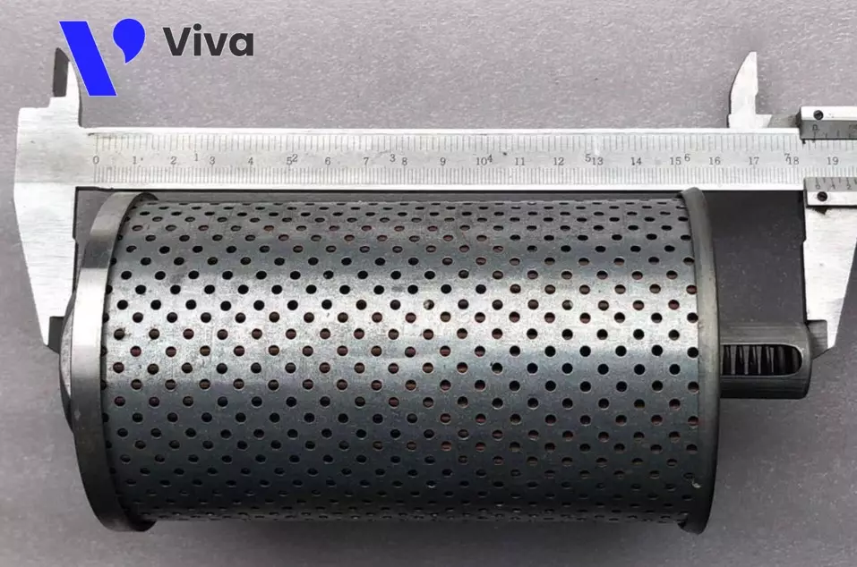
Hydraulic Oil Filter
The hydraulic oil filter has the function of preventing dirt and contaminants present in the hydraulic oil from flowing into the hydraulic components. Initially, hydraulic oil used in production undergoes refining and removes various impurities. However, during long-term operation, contaminants can accumulate due to factors such as:
Dust entering the oil reservoir.
Metallic debris formed by friction between internal components of the system.
Prolonged operation in unfavorable conditions, leading to the formation of dirt.
If these impurities enter the hydraulic equipment along with the hydraulic oil flow, it can adversely affect the equipment’s performance (resulting in unstable operation, reduced durability, or even equipment damage).
Therefore, oil filters are typically installed at the inlet of the oil pump’s suction line to prevent dirt from entering the operating hydraulic equipment in the system.
Transmission and Control Components
After the hydraulic oil is drawn up from the reservoir, the flow through the pump reaches a certain pressure threshold. To perform the functions of transmitting power and controlling the mechanisms and devices, this oil flow needs to be supplied to the hydraulic equipment.
Based on the characteristics of the oil used within the hydraulic system, there is a tendency to reach positions with higher pressure. To achieve this, pipes with high-pressure and temperature-resistant capabilities are used in combination with various types of valves as essential components for transmission and control.
Hydraulic Oil Lines
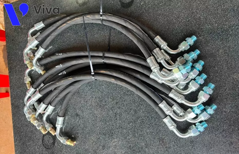
Hydraulic oil lines, also known as fluid lines, are essential components of the system. They are used to transmit hydraulic fluid, typically oil, from the pump to other mechanical components within the system.
Fluid lines are usually made from materials such as oil-resistant rubber, PVC, nylon, or stainless steel. The material chosen depends on the specific requirements of the application and factors such as working pressure (ranging from 30 bar to 700 bar and more), ambient temperature, and the type of fluid used.
Hydraulic fluid lines come in different diameters and thicknesses to suit the system’s requirements. The diameter of the lines is selected based on the flow rate of the transmitted fluid, while the thickness of the lines is designed to withstand the working pressure of the system.
Fluid lines are connected to each other using couplings or fittings. For high-pressure applications that require high durability, the lines can be reinforced with braided fibers to increase stiffness and pressure resistance.
Types of Hydraulic Valves
Hydraulic valves are directly installed on the pipelines to allow users to control and regulate the flow of hydraulic oil within the system. Different types of valves serve different functions. Some common types of hydraulic valves include:
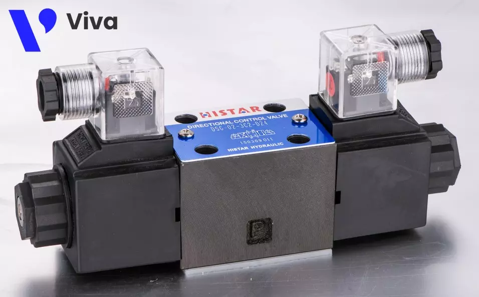
Directional Valve
A hydraulic directional valve is used to control the direction of fluid flow in a hydraulic system. It enables the operator to switch the fluid flow through different pipelines to achieve control functions.
Directional valves can be controlled electrically, directly operated through lever mechanisms, or controlled by diverting a small portion of the hydraulic oil to control the valve (depending on the specific product type).
Safety Valve
A hydraulic safety valve, also known as a hydraulic relief valve, is used to protect the system and its components from overpressure.
The valve is designed to automatically open when the hydraulic oil pressure in the system reaches a certain threshold. The opening limit of the valve can be adjusted to suit the specific usage requirements. The oil flow after passing through the valve is directed back to the reservoir through a separate pipeline.
The main purpose of the hydraulic safety valve is to ensure that the fluid pressure does not exceed the safe limit, preventing system damage or leakage and maintaining stable system operation. When the fluid pressure exceeds the set level, the safety valve opens and allows the fluid to flow through, reducing the pressure.

Check Valve
A hydraulic check valve, also known as a one-way valve, is a type of valve that controls the flow of fluid in a hydraulic system. This valve is designed to allow fluid flow in only one direction, preventing backflow.
This device has a relatively simple construction, with the main component being the valve body inside which a valve disc (in the shape of a metal disc or a ball) is fitted and pressed by a spring in one direction. During operation, when the high-pressure hydraulic oil flows in one direction opposite to the force exerted by the spring, it opens the valve. In the reverse direction,
When fluid pressure acts on the valve from the open side, the valve opens and allows the fluid to flow through. However, when fluid pressure acts on the valve from the closed side, the valve closes tightly and prevents backflow. The pressure from the upstream flow combined with the spring force will keep the valve closed. Thus, the check valve only allows hydraulic oil to flow in a specific direction.

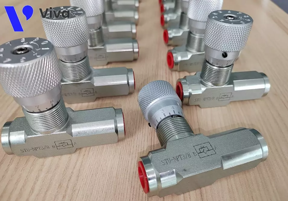
Flow Control Valve
A hydraulic flow control valve, also known as a hydraulic flow control check valve, is a type of valve used in hydraulic systems to control the flow of fluid (typically hydraulic oil). The main function of the flow control valve is to regulate the fluid flow through the system and control the pressure.
Hydraulic flow control valves are often designed with a mechanical or electronic valve that can be manually or automatically controlled. This valve can adjust the cross-sectional area of the valve body to expand or contract, creating a narrower or wider area within the pipeline. When the valve is adjusted, it affects the flow of fluid in the system.
Monitoring Components
Monitoring components are measurement devices commonly found in hydraulic systems. They are used to test and evaluate physical quantities related to the operation of hydraulic oil within the system, including pressure, temperature, oil level, etc.
Pressure Gauge
Pressure gauges are directly installed on the pipeline system or on certain parts and equipment of the system. During operation, a portion of the hydraulic oil will flow into the gauge, and the pressure value will be displayed on the gauge.
Based on the measured pressure value combined with the intended use, users can adjust the pressure to the appropriate value according to the technical requirements during operation.

Temperature Gauge
Along with pressure, temperature greatly affects the operation of hydraulic equipment. During operation, hydraulic oil heats up, which is a normal phenomenon. However, the temperature range needs to be ensured within a certain limit (conventional hydraulic oils operate within the range of -40°C to 70°C, while some special types can withstand temperatures up to 150°C).
Therefore, temperature gauges are used to allow users to monitor the temperature index of the system, enabling assessment and adjustment to ensure suitability.

Oil Level Sensor
To ensure the system always maintains stable operation, the hydraulic oil level inside the oil tank needs to be maintained at an adequate level. In many cases, it is difficult to observe the actual oil level inside, and therefore, oil level sensors are necessary.
They can be simple float mechanisms that can be visually observed or oil sight glasses with graduated markings. Moreover, there are sensor devices capable of providing data to the central control computer.
Actuating Components
Actuating components include devices that receive high-pressure hydraulic oil flow to perform specific operations within the system.
Hydraulic Cylinder
The hydraulic cylinder is a fundamental component in hydraulic systems. It is a device that converts hydraulic energy into mechanical motion. Hydraulic cylinders are commonly used to generate pushing or pulling forces in industrial and mechanical applications.
A hydraulic cylinder consists of two main components: the cylinder and the piston. The cylinder is a cylindrical tube made of durable materials such as steel, and it is sufficiently sealed to prevent hydraulic oil leakage. The piston is a cylindrical rod tightly fitted within the cylinder and can move along the length of the cylinder.
When hydraulic oil is introduced into the cylinder through a pipeline, the oil pressure causes the piston to move inside the cylinder, generating pushing or pulling forces. When the hydraulic pressure is released or reduced, the piston moves in the opposite direction, and the hydraulic oil returns to the supply source, resulting in the operation of the cylinder.
Hydraulic cylinders can be used in various applications, including industrial machinery, construction equipment, automobiles, tractors, and mechanical systems.

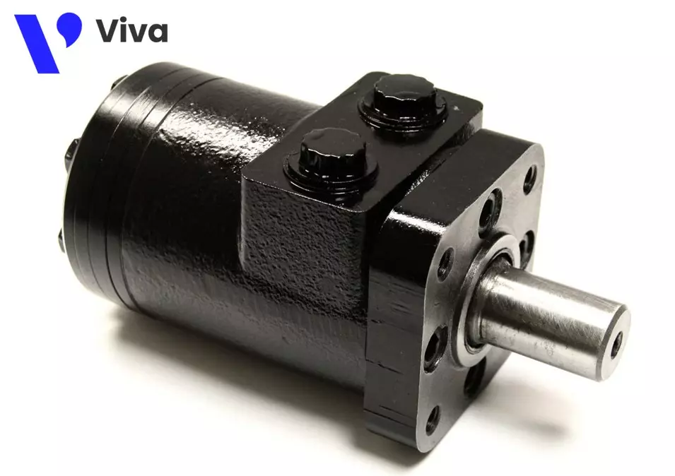
Hydraulic Motor
Along with hydraulic cylinders, hydraulic motors are known as commonly used hydraulic devices. These devices are used to convert hydraulic energy into rotational motion. This motion is utilized to drive other mechanisms or devices.
Physical Quantities Related to Hydraulic Systems
During the design and operational processes of hydraulic systems, engineers and technicians rely on physical quantities to evaluate and adjust the working conditions. For hydraulic systems, important physical quantities include:
The important physical quantities related to hydraulic systems are:
- Pressure: This quantity measures the force acting on a certain area. In hydraulic systems, pressure is typically measured in units of Pascal (Pa) or pounds per square inch (psi).
- Flow rate: This quantity measures the mass or volume of fluid passing through a point in the system per unit of time. Flow rate is usually measured in cubic meters per second (m³/s) or gallons per minute (GPM).
- Fluid velocity: This quantity measures the speed of fluid movement within the system. Flow velocity is typically measured in meters per second (m/s) or feet per second (ft/s).
- Force: This quantity measures the ability to act and move components within the hydraulic system. Force is usually measured in units of Newton (N) or pound-force (lbf).
- Power: This quantity measures the ability to perform work or generate hydraulic tool output. Power is typically measured in units of Watt (W) or horsepower (hp).
- Torque: This quantity measures the force that causes an object to rotate around an axis. In hydraulic systems, torque is typically measured in units of Newton meters (N·m) or pound-force feet (lbf·ft).
These quantities play a crucial role in describing, measuring, and controlling the parameters and performance of hydraulic systems.
Applications of Hydraulic Systems
Hydraulic systems are widely used in various fields. Here are some common applications of hydraulic systems:
- Industrial Manufacturing: Hydraulic systems are commonly used in heavy industrial plants. They perform functions such as lifting, lowering, and moving objects from one area to another. Hydraulic systems are integrated into various types of machinery, ranging from simple hydraulic jacks and hand pumps to more complex machinery and equipment like robotic arms.
- Transportation: Hydraulic power transmission systems are integrated into many types of vehicles. The most familiar examples include the hydraulic brake system in motorcycles and the steering systems of cars, trucks, as well as hydraulic power transmission systems in airplanes and ships.
- Construction: Hydraulic systems are used in construction machinery such as excavators, bulldozers, and pile drivers. These machines rely on hydraulic systems to operate specific mechanisms.
These are some common examples of hydraulic system applications.

Conclusion
In reality, hydraulic systems play a vital role in various industries and industrial applications. Thanks to their power and flexible control, hydraulic systems have become an indispensable technology for performing tasks such as lifting, lowering, rotating, and controlling machinery and equipment.
Although hydraulic systems bring many benefits, they also present some challenges. Common issues include leakage, pressure loss, noise, and regular maintenance requirements that users of hydraulic systems have to face. To ensure efficient and reliable operation of the system, regular maintenance and the use of high-quality materials are crucial.
Overall, hydraulic systems play a crucial role in various industries and industrial applications. Their flexibility, high performance, and controllability bring numerous benefits and improve work efficiency. Despite requiring strict management and maintenance, hydraulic systems remain an important and reliable technology in the industrial and engineering sectors.
This concludes the basic knowledge sharing about hydraulic systems. If you have any requests or feedback regarding the article, feel free to contact us directly or leave your questions and contributions in the comments section.
Thank you!


