Pneumatic directional control valve
Giá gốc là: 99.000 $.65.000 $Giá hiện tại là: 65.000 $.
Cập nhật lần cuối ngày 13/08/2025 lúc 10:45 sáng
The compressed air directional valve is present in almost all compressed air systems, with a variety of operating methods designed to control the direction of compressed air flow in the system. If you need to find more information about this product, I hope this article can provide you with useful information.
What is a Pneumatic Directional Control Valve?
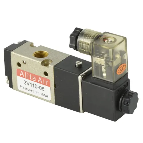
The pneumatic directional control valve, also known as “Van điều hướng khí nén” in Vietnamese, is a type of device used in compressed air systems to regulate the flow direction of compressed air to different pneumatic pipelines. It can control the supply or exhaust of compressed air to the external environment.
The control of the device can be achieved through electromechanical force, lever mechanisms, or pneumatic pressure.
The valve body is designed with connecting ports, which are used to connect with pneumatic hoses or to link with pre-designed ports on the valve base.
In the industry, directional control valves are widely used in large quantities. They are often designed to be connected to form pneumatic valve clusters, meeting the complex operational requirements of industrial systems.
The valve body is usually made of aluminum alloy, and its internal structure for guiding compressed air varies depending on the desired control functions for different air flow directions. In Vietnam, this device is known by various names such as:
- Pneumatic valve
- Pneumatic distribution valve
- Pneumatic reversing valve, etc.

Structure of a Pneumatic Directional Control Valve
Pneumatic Directional Control Valves are manufactured in various types, and among these types, there are differences in terms of valve body shape or control mechanisms. However, they share a common basic design principle.
To better understand the structure of this valve, let’s explore the structure of an electromagnetically controlled Pneumatic Directional Control Valve. The device is composed of the following main components:
- Valve Body: The valve body is made of aluminum alloy and is internally machined to form air distribution channels. It is combined with the adjustment of the valve spool position to change the flow direction of compressed air.
- Spool: The valve spool is typically made of aluminum and is placed vertically inside the valve body. It rotates and has rubber seal details that move along the valve body. This movement is facilitated by the elastic force from springs and compressed air.
- Solenoid Coil: This component is formed by winding multiple turns of copper wire around a hollow core. The coil is protected by an outer molded plastic layer. The coil is designed with wire lead ends to receive control current from the outside.
- Spring: This component generates a continuous restoring force that acts on the valve spool to maintain the valve in a certain fixed state when there is no control signal from the user.
- Valve Cap: The valve cap can be seen as part of the valve body. It seals and completes the device, and is fixed to the valve body using fastening screws.
- Fastening Screws: These components are typically made of steel and coated with anti-corrosion material on the outside. They are responsible for connecting and securing the various parts together.
In addition to the main components mentioned above, to form a complete device, there are also auxiliary components, including: valve body gaskets, fixed knob for coil, wire terminal protective casing, etc.

How does a Pneumatic Directional Control Valve work?
When discussing the operating principle of a Pneumatic Directional Control Valve, it is important to understand the general concept as follows.
On the body of the Pneumatic Directional Control Valve, there are ports designed for connection to pneumatic hoses with the assistance of quick pneumatic connectors.
Inside the valve body, there are specially designed air chambers. These chambers, in combination with the unique structure of the valve spool, control the direction of the compressed air. The pneumatic operation of the valve is achieved by changing the position of the valve spool. To control the working position of this component, manufacturers apply various methods depending on the intended use. These methods may involve electromagnetic forces, the pressure of the compressed air, or mechanical linkage mechanisms.
To better understand the operation of a Pneumatic Directional Control Valve, let’s explore the following example:
To control a single-acting pneumatic cylinder as shown in the image below, a 3-way 2-position pneumatic directional control valve is used. One end is actuated by an electromagnetic force, and the other end is actuated by the restoring force of a spring (the pneumatic system is set up as shown in the image below).
- In position 1: When we supply an appropriate current (AC 220V, DC 24V, etc., depending on the valve type) to the coil (solenoid coil), an electromagnetic force is generated inside the coil. At this point, the coil acts as an electromagnet and pushes the iron core inside the valve body, which indirectly affects the valve spool. As a result, the valve spool is pushed to the left. Due to the special structure of the spool and valve body, the air path from port 1 to port 3 is opened. Compressed air from the air compressor flows through the valve and reaches the pneumatic cylinder.
- In position 2: The valve shifts to working position 2 when we stop supplying power to the solenoid coil. Since there is no current supplied, the coil does not generate an electromagnetic force on the iron core. Therefore, under the influence of the restoring force from the spring, the valve spool is pushed to the right (as indicated by the arrow in the image below). When the valve spool is shifted to the left, it opens the air passage connecting port 3 to port 2, while port 1 is blocked. The compressed air inside the cylinder is then directed back to the valve through port 2 and released to the outside.
The above explanation represents a complete working cycle of one type of Pneumatic Directional Control Valve commonly used in industries. Depending on the specific design of each product, there may be slight variations in the operating mechanism, but the basic working principle remains the same.

Air Compressor Directional Valve Classification
To meet various working conditions, it is necessary to manufacture valves in different types. So, what types of compressed air directional valves are provided? Let’s find out below.
Classification based on control method
Solenoid-controlled compressed air directional valve
Considering the structure of the device, it uses one or two solenoid coils at the valve’s ends. These coils use electric current to generate a strong electromagnetic force that acts on the iron core inside the valve body. Solenoid-controlled compressed air directional valves are widely used due to their advantages of easy integration into automatic control systems and compatibility with various sensors.
In the current market, these devices are supplied with options for control current, including AC 220V, AC 110V, DC 12V, DC 24V, etc. Additionally, this product line offers variations with either one coil or two coils.
Furthermore, the valve body is designed with a direct impact button, allowing users to adjust the valve directly in case of power supply failures.

Toggle-type Pneumatic Directional Valve
Fundamentally, the toggle-type pneumatic directional valve operates similarly to the solenoid-controlled type. However, instead of using electromagnetic force for actuation, this type of device employs a toggle mechanism connected to the valve stem to control the valve.
This device has the advantage of high durability and simple adjustment operation, without the need for electrical power to operate the valve. However, it has certain limitations, such as the inability to operate remotely. For large and complex systems, the use of this device does not ensure synchronization.
Based on these characteristics, toggle-type pneumatic directional valves are used in individual positions to directly control specific components.

Pneumatically Controlled Pneumatic Directional Valve
For pneumatically controlled pneumatic directional valves, the force acting on the valve stem is generated by the high-pressure pneumatic flow itself.
This type of valve has outstanding durability and the ability to be remotely controlled. However, it needs to be combined with other similar electronic devices.

Classification based on the number of valve ports
2/2 Pneumatic Directional Valve
The 2/2 pneumatic directional valve is designed with two ports on the valve body, connecting to pneumatic conduits. These two pneumatic paths correspond to an outlet path and an inlet path. The valve’s two positions correspond to the open and closed positions.
With this design, the valve is used to perform a single function, which is to open or close the flow of compressed air passing through the valve.

3/2 Pneumatic Directional Valve
The 3/2 pneumatic directional valve is designed with 3 ports on the valve body, which correspond to:
- Air supply port: This port is connected to the air supply line, allowing compressed air from the air compressor to enter the valve body.
- Outlet port: The outlet port is connected to a conduit to supply compressed air to the components and devices behind the valve. It is commonly connected to single-acting pneumatic cylinders to control the operation of these pneumatic devices.
- Exhaust port: This port is used to exhaust compressed air to the outside when the air flow is reversed.
The 2 positions of the device correspond to the air supply position and the exhaust position.

5/2 Pneumatic Directional Valve
The 5/2 pneumatic directional valve is designed with 5 different ports on the valve body, which include:
- A supply port: The supply port is usually marked as (P), and it allows compressed air to enter the valve body through this port.
- 2 outlet ports: The two outlet ports are marked as port A and port B. They are typically connected to the two air supply lines of a double-acting pneumatic cylinder to control the stroke of this device.
- 2 exhaust ports: The two exhaust ports are marked as R and S. During the change of working position, compressed air from port A is exhausted to the outside through port R, and port B is exhausted through port S.
The two working positions of the valve include: the position where air is supplied through port A and the remaining position where air is supplied through port B.

5/3 Pneumatic Directional Valve
The 5/3 pneumatic directional valve is a valve with 5 ports and 3 positions. It is designed with 5 ports on the valve body, similar to the 5/2 valve, including ports P, A, B, S, and R. However, this type of valve has an additional working position, which is the position where the air supply is completely stopped or simultaneously supplied to both ports A and B (depending on the design).

Trends in the Future Development of Pneumatic Directional Valves
Pneumatic directional valves have been used in various applications, especially in industrial systems, where they are combined with other pneumatic devices in compressed air systems, such as:
- Pneumatic cylinders
- Pneumatic motors
- Pneumatically operated machinery, etc.
They contribute to improving work productivity, ensuring synchronization for the produced products, and reducing labor requirements. Throughout their application history, these valves have been continuously improved and developed in terms of structure, materials, and the ability to work under high intensity. In the near future, with the strong explosion of advancements in science and technology, these products are highly likely to be integrated with IoT technology, AI, and various sensors to further optimize their automation capabilities.

Applications of Pneumatic Directional Valves
Pneumatic directional valves have a wide range of practical applications in various industries and automation systems. Here are some typical applications of these devices.

Control of Pneumatic Cylinders
Pneumatic directional valves are used to control pneumatic cylinders in industrial and automation applications such as steel rolling, door opening/closing, food production, and packaging.
Control of Machine Tools
Pneumatic directional valves are used to control various types of machine tools that utilize compressed air, such as drilling machines, metal cutting machines, and grinding machines.
Control of Other Devices and Components in the System
Pneumatic directional valves are also used to control other devices or components in compressed air systems, including adjusting the direction of compressed air flow to different pipe branches within factories or workshops, as well as in power transmission devices such as slides and speed regulators.
Pneumatic Directional Valve Products Provided by VIVA
VIVA Company is one of the leading suppliers of pneumatic directional valve products in Vietnam. We specialize in providing high-quality products with various types and designs to meet different customer requirements.
Our products are imported from multiple brands, covering a wide range from low-end to high-end, including:
- Airtac from Taiwan
- STNC from China
- SMC from Japan
- Festo from Germany, and more
All the products we provide are guaranteed to be genuine, and the selected brands meet global standards in terms of design and manufacturing. Therefore, customers can be completely confident in the integration capability of these devices into their systems.
Furthermore, our supplied products are accompanied by warranty policies and technical support, including solution consultation and technical advice.
We appreciate the time you have dedicated to reading this article!
We warmly welcome any feedback and are always ready to address related inquiries.

ĐÁNH GIÁ SẢN PHẨM
Hãy là người đầu tiên nhận xét “Pneumatic directional control valve”

Đánh giá
Chưa có đánh giá nào.