Types of pneumatic valves
For a long time, compressed air systems have played an important role in various industries and fields, enabling efficient and cost-effective control and regulation of systems. As a result, different types of pneumatic valves have been developed.
In today’s article, we will explore the types of compressed air valves, their functions, and operations.
What are compressed air valves?
Compressed air valves, also known as flow control valves for compressed air, is a general term used to refer to various types of valves used in compressed air systems. The specific function of a valve depends on its type, for example:
- Directional control valves for compressed air: These devices control the flow of compressed air in different directions through various pipelines.
- Pressure control valves for compressed air: These devices are used to regulate the pressure of compressed air after it passes through the valve.
- Flow control valves for compressed air: With these devices, we can adjust the flow rate of compressed air within a certain range in the pipelines.
- Safety valves for compressed air: These valves serve to protect the system from incidents caused by excessively high working pressure compared to the design standards.
There are many other types of valves, which we will explore further in the following sections of the article.
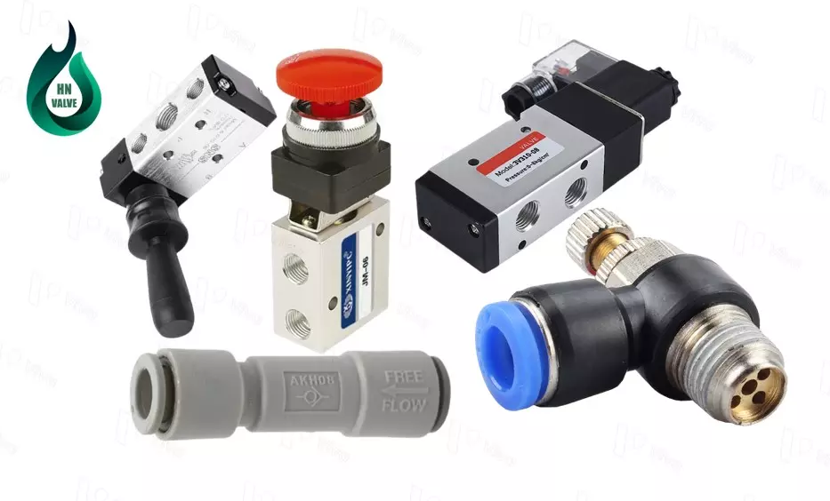
Unlike industrial valves, which are designed in large sizes, compressed air valves are usually manufactured in small sizes. They are made from a variety of materials, including aluminum alloys, stainless steel, plastics, and bronze alloys.
Most compressed air valves are designed for use in pressure ranges from 0 bar to 10 bar. Some special applications may require these devices to withstand pressures of up to several tens of bars. In general, compressed air valves have lower temperature and pressure thresholds compared to industrial valves.
Classification of compressed air valves
Compressed air systems have been applied and developed for a long time, and over time, there have been increasingly diverse types of compressed air valves, along with variations of those valves, to meet specific working requirements. Based on the function of each valve, we have the following main types of valves.
Directional control valves for compressed air
The directional control valve for compressed air is the most widely used valve in compressed air systems. This device is used to change the direction of the compressed air flow to different pipelines (each pipeline corresponds to a specific direction).
To control the flow of compressed air in different directions, the valve body is designed with ports connected to separate pipelines. By changing the position of the piston inside the valve body, compressed air from the inlet port (P port) is distributed to different ports.
Some other names for directional control valves for compressed air used in Vietnam include:
- Distribution valve for compressed air
- Compressed air valve
- Electropneumatic valve,…
To meet the increasing demand for high-performance requirements set by compressed air systems, directional control valve devices have been developed with more diverse types over time. Based on different aspects, we can classify directional control valves into the following types.
Classification based on control method
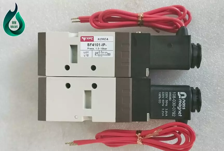
The control method of directional control valves for compressed air refers to the method used to generate force to change the working position of the piston, thereby changing the operating mode of the valve. The following are the types of actions:
- Control through electromagnetic force: At the valve’s head, a coil is designed, which transforms the electrical current to generate a magnetic field. This magnetic field affects a steel core (attracts and moves the steel core). When the steel core changes its position, the compressed air in the system is diverted to a specific direction by interacting with the piston. When the electric current supplied to the coil is interrupted, the magnetic field is lost, and the spring placed inside the valve body pushes the steel core and piston back to the initial position.
- Control through external force: There are two common design types applied to directional control valves that operate through the action of an external force. The first is a lever-operated directional control valve, where a mechanism is designed to directly receive the control force applied by a person (lever mechanism or push-button mechanism). Another type is the roller-operated pneumatic directional control valve. This device is designed with a roller connected to a lever so that when a specific component in the system moves and comes into contact with the roller during its travel, the force is transmitted through the lever to change the working state of the valve.
- Control through compressed air: Compressed air from the system, through various control and distribution devices, is extracted to control the main directional control valve device.
The above are some common operating control methods of directional control valves for compressed air. Currently, to meet the requirements of systems operating with high precision and automation capabilities, these devices are often integrated with various types of sensors to enhance accuracy and automatic operation.
Classification based on valve body structure
The valve body structure directly affects the features that the device can provide. The valve body structure we are referring to here is the difference in the structure of the valve body and the valve spool.
- 2/2 compressed air directional control valve: The valve body is designed with 2 ports (1 inlet port and 1 outlet port), and there are two working positions of the piston corresponding to the closed position and the open position.
- 3/2 compressed air directional control valve: The valve body is designed with 3 ports (1 inlet port, 1 exhaust port, and 1 outlet port). Two positions correspond to the valve’s open position, where compressed air flows from the inlet port to the outlet port, and the remaining position corresponds to the air cut-off mode. At the same time, the compressed air in the system is exhausted after completing a working cycle.
- 5/2 compressed air directional control valve: The valve has 5 connecting ports (1 inlet port, 2 outlet ports, and 2 exhaust ports). Two working positions of the piston correspond to supplying compressed air to one of the outlet ports and exhaust air from one of the exhaust ports.
- 5/3 compressed air directional control valve: The valve is designed with 5 ports on the valve body, similar to the 5/2 valve. However, this device has a piston that can be in three different working positions.
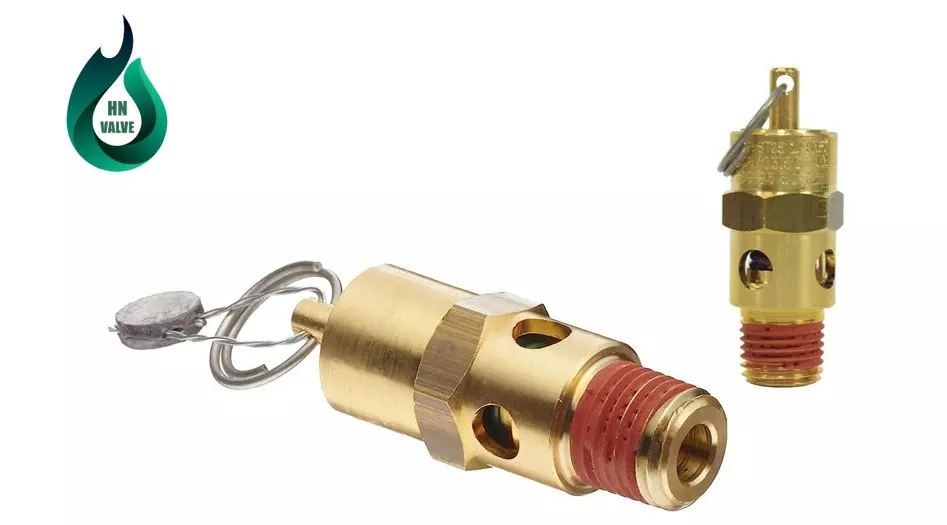
Pneumatic Safety Valve
A pneumatic safety valve is one type of compressed air valve used in pneumatic systems to protect the system from excessive and dangerous pressures. The main function of the pneumatic safety valve is to automatically reduce pressure when the pressure in the system exceeds the set safety level.
On top of the valve body, there is a pressure relief adjustment component that allows us to adjust the working pressure limit of the valve through this part.
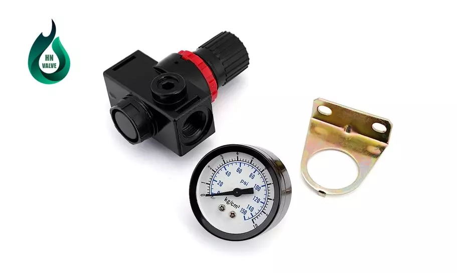
Pneumatic Pressure Regulator Valve
Pneumatic pressure regulator valves are devices used in pneumatic systems to regulate and maintain the compressed air pressure at a predetermined level.
Some characteristics and functions of pneumatic pressure regulator valves include:
- Pressure adjustment: Allows the user to adjust the output compressed air pressure according to specific system requirements.
- Maintaining stable pressure: Pneumatic pressure regulator valves ensure that the output compressed air pressure remains stable, unaffected by variations in input pressure. This ensures stability in the operation of other pneumatic components and devices in the system.
Pneumatic pressure regulator valves play a crucial role in ensuring the stable and safe operation of pneumatic systems. Selecting and using the appropriate pressure regulator valve according to the system’s requirements is essential to ensure optimal performance and reliability of the pneumatic system.
Pneumatic Flow Control Valve
Pneumatic flow control valves are devices used in pneumatic systems to regulate the flow of compressed air through conduits. The main function of the pneumatic flow control valve is to adjust or restrict the flow rate to meet specific application requirements.
Some characteristics and functions of pneumatic flow control valves include:
- Flow rate adjustment: Allows the user to adjust the flow rate of compressed air through the conduits. By adjusting the position of the valve, the user can increase or decrease the flow rate of compressed air to meet the requirements of a specific process or device.
- Speed control: Used to control the movement speed of pneumatic-controlled components, such as pneumatic cylinders. By regulating the flow rate of compressed air, the valve helps control the movement speed to achieve precise processes and operations.
- Various connection types: Pneumatic flow control valves can have multiple connection types, including threaded, flanged, or port connections. This allows for easy installation and connection of the valve into the pneumatic system.
Pneumatic flow control valves are widely used in pneumatic applications such as control systems, industrial machinery, and automated processes. Selecting and using the appropriate flow control valve based on the application’s requirements and technical specifications is important to ensure stable operation and optimal performance of the pneumatic system.

One-way compressed air valve
A one-way compressed air valve is used in compressed air pipeline systems to ensure that compressed air can only move in one direction. This type of valve operates independently. The valve allows compressed air to pass through in the forward direction, while it blocks the airflow in the opposite direction. This device can achieve this because it has a spring mechanism that always applies a spring force to push the valve in one direction.
In the forward direction, the pressure of the compressed air acts on the valve. If this pressure is high enough, it overcomes the spring force and opens the valve. In the reverse direction, the pressure of the compressed air acts on the valve, generating a thrust force in the same direction as the spring force. As a result, the valve closes.

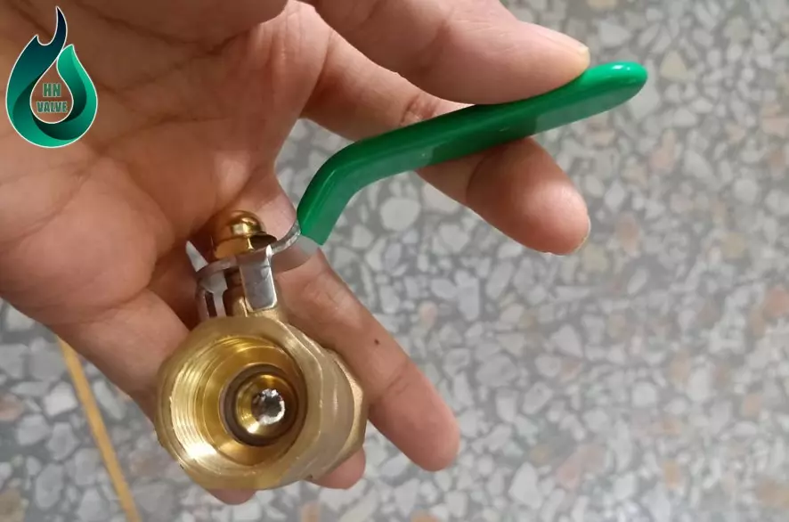
Compressed air shut-off valve
These types of valves have the function of completely shutting off or opening the compressed air conduits. They are used in large-sized pipelines, typically in main pipelines or branch pipelines supplying air to specific areas or components.
Based on their function and operating conditions, these devices are used to fully shut off or open positions at the beginning or end of the system. The types of valves that can be used to control the flow of compressed air are usually ball valves or gate valves.
Understanding the Symbols of Different Valves in Compressed Air Systems
In practice, when reading technical documents related to workshop compressed air systems or various types of machinery, these systems are often represented in the form of diagrams. Compressed air equipment, including air valves, is represented by different symbols to facilitate research and system design.
Let’s explore together the various types of compressed air valves and how they are represented in compressed air system diagrams.
Symbols for Different Compressed Air Valves
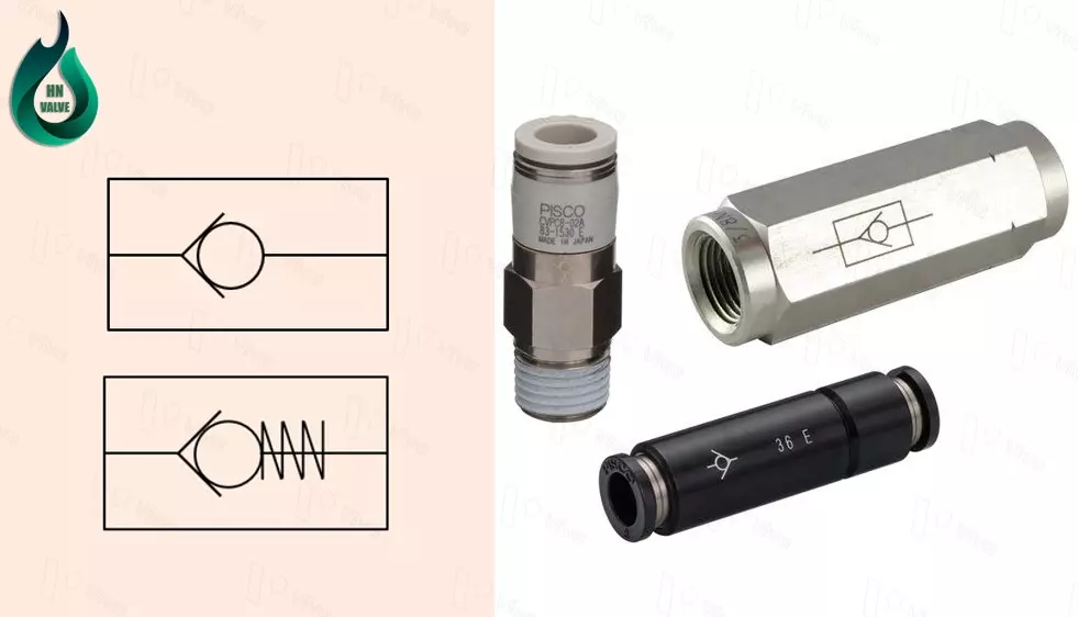
One-way Valve Symbol
A one-way compressed air valve is represented by a circular symbol enclosed within a triangular funnel shape. The circular shape represents the metal ball inside the valve body (some types may use a plug instead of a ball), while the two straight lines on either side represent the compressed air flow paths connected to the ends of the valve.
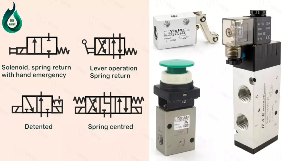
Directional Valve Symbol
Among the various types of valves used in compressed air systems, directional valves come in the widest variety. Therefore, the symbols for directional valves can vary based on the control method, the number of valve ports, and the number of working positions of the piston.
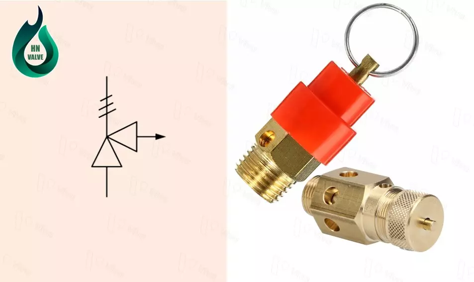
Safety Valve Symbol
A compressed air safety valve is installed in pipelines or pressure vessels to ensure the safety of equipment. The valve is symbolized by two triangular shapes, with one direction indicating the incoming compressed air and the other direction representing the release of compressed air from the valve. The valve is designed with a spring mechanism to generate a force in the opposite direction of the working pressure. The spring force can be adjusted by a bolt detail to change the compression force of the spring.
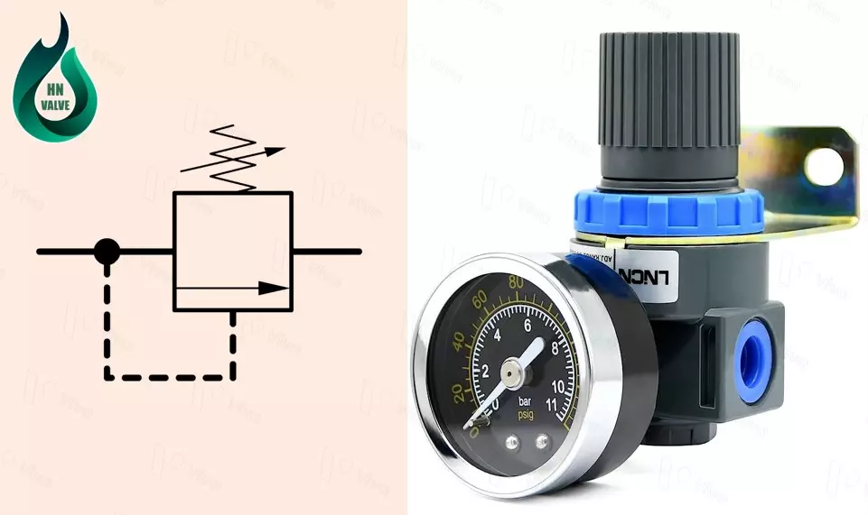
Pressure Control Valve Symbol
To better understand the symbol of a compressed air pressure control valve, let’s explore its basic operation.
A compressed air pressure control valve allows users to adjust the output pressure of compressed air within a specific range and maintain a stable pressure throughout the working process. In the initial stage of air supply, the system behind the valve has a lower pressure than the system in front of the valve, allowing compressed air to pass through easily.
After a certain period of air supply, the pressure of the compressed air behind the valve gradually increases to a certain level. The pressure of the compressed air acts on a diaphragm, causing it to move. The diaphragm is connected to the valve stem and disc, so when the diaphragm moves, it pulls the stem and disc, thereby closing the valve. The compressed air is then directed back to the position in front of the valve (the return path of compressed air is represented by the valve symbol with a broken line).
Diagrams of Systems Applying Various Types of Pneumatic Valves
Compressed air systems are widely used in industry and various types of machinery. Depending on the functions that a compressed air system needs to perform, they can have different levels of simplicity or complexity.
The more functions a compressed air system needs to fulfill, the more complex it becomes, and it consists of different types of pneumatic devices.
To better understand the functions of various types of pneumatic valves, let’s explore some basic pneumatic circuit diagrams together.
Diagram of Double-Acting Pneumatic Cylinder Control
In a circuit controlling a cylinder, we use a 5/2 directional solenoid valve, with the return direction using a spring.
Compressed air from the source is supplied to the valve through port 1 as shown in the diagram. This valve controls the direction of the compressed air flow, either in one of the two pipe directions connected to the ends of the cylinder.
Two flow control valves are installed on each pneumatic line to control the speed of movement of the pneumatic cylinder during operation.
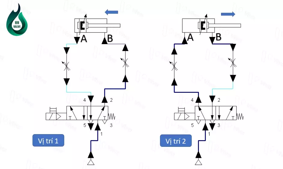
The operating control circuit of a pneumatic cylinder operates as follows:
Position 1: When the directional valve is not powered, meaning that the coil inside does not generate a magnetic field, the internal piston of the valve is pushed to the left by the force of the spring. Compressed air from port 1 flows through the valve body and exits through port 2, entering port B of the cylinder through the pneumatic line. The pressure of the compressed air acts on the piston, pushing the moving element inward.
The volume of air in the opposing chamber, due to the volume change, is expelled through port A, passes through the directional valve, and then exits through port 5.
Position 2: When electrical power is applied to the coil, it generates a magnetic field that attracts the steel core inside the valve. The movement of the steel core opens a path for the compressed air, and the pressure of the compressed air, through a special mechanism, creates a large force that acts on the piston, pushing it to the right.
At this point, compressed air from port 1 is directed to port 4, through the pneumatic line, to enter port A of the cylinder and push the cylinder shaft to move to the right as indicated by the arrow.
In the opposing chamber of the pneumatic cylinder, the previously existing compressed air flows back through port B, passes through the directional valve, and exits to the environment through port 3.
Diagram of Single-Acting Pneumatic Cylinder Control
To control a single-acting pneumatic cylinder, a 3/2 directional solenoid valve with spring return is used, and a flow control valve is used to control the speed of the pneumatic cylinder’s stroke.

Initially, without supplying air and under the influence of the spring’s recoil force placed inside the cylinder body, it exerts force on the piston and pushes the entire shaft and piston mechanism inward into the cylinder body. Then, when the pneumatic operation of this system is activated, the following will occur:
Position 1: When the directional valve is not powered, the spring’s recoil force acts on the piston, pushing it to move to the left. At this point, compressed air from port 1 flows to port 2 through the flow control valve, and then enters the inside of the pneumatic cylinder body. With sufficient pressure, the compressed air acts on the piston, creating a force opposite to the recoil force of the spring. This force pushes the cylinder shaft outward.
Position 2: When the directional valve is powered, the electromagnetic force acts on the steel core and changes its position, causing a portion of the compressed air to be diverted to impact the piston’s position.
At this point, the compressed air from port 1 is blocked and cannot pass through the valve. Instead, the compressed air that existed in the cylinder in the previous process reverses back to the valve and exits to the environment through port 3.
The above describes the two most basic pneumatic circuit diagrams used to control pneumatic cylinders. Through this, we can understand the fundamental functions of some types of pneumatic devices and how they operate within a system.
Conclusion
This article has discussed various types of pneumatic valves, clarifying their functions and operational principles.
Furthermore, the article has addressed different variations of directional control valves, which have been improved in terms of valve body structure and operational methods to optimize their performance in specific working conditions.
For the purpose of providing a brief introduction to pneumatic valves, this article does not delve into aspects such as construction, detailed operation, and technical specifications. However, we have included specific links for readers who wish to explore each type of valve in more depth.
Finally, I would like to sincerely thank you for taking the time to read this article and I greatly appreciate any feedback or contributions from our readers.
